|
|

|
Cross Profile Formats |

|

|

|

|

|
||
|
Cross Profile Formats |
|
|
|
|

|

|
Cross Profile Formats
|
|
|
Cross Profile Formats |
|
|
|
|
|
||
|
Cross Profile Formats |
|
|
|
|
|
|
A variety of Cross Profile Data Formats can be Imported. The Format Types are hard-coded into AutoChart and details of the currently available file types are given below:
The Caris HIPS Format is a comma delimited X,Y,Z file with each cross profile separated with the string ,,---. Note that depths should be stored as negative values.
AutoChart assumes that the cross profile is exactly perpendicular to the route. It takes the first point in the cross profile and calculates its Kp in relation to the route. AutoChart then parses the cross profile and finds the point closest to the route (i.e. the nearest DCC to Zero). This point's Z value is then used as the reference for the profile so that all other points are plotted relative to it.
Data Example
371561.79,4450973.04,-2.739
371561.71,4450972.98,-2.740
371561.62,4450972.93,-2.740
371561.54,4450972.88,-2.740
371561.45,4450972.83,-2.737
371561.36,4450972.78,-2.734
371561.28,4450972.73,-2.731
371561.19,4450972.68,-2.729
371561.10,4450972.63,-2.727
,,---
371588.61,4450977.19,-2.918
371588.52,4450977.14,-2.917
371588.43,4450977.09,-2.916
371588.35,4450977.04,-2.917
371588.26,4450976.99,-2.919
371588.18,4450976.94,-2.922
371588.09,4450976.89,-2.924
371588.00,4450976.84,-2.924
371587.92,4450976.79,-2.917
371587.83,4450976.74,-2.908
371587.74,4450976.68,-2.899
371587.66,4450976.63,-2.892
371587.57,4450976.58,-2.886
371587.49,4450976.53,-2.881
The Geoconsult Cross Profile File Format is a semicolon delimited file with the extension ".gcp" (Geoconsult Cross Profile). The data in the file should consist of a header part and a data part.
The Header part of the cross profile file consists of the first three lines of the file and the first character of each line is a hash"#". The first line denotes the name of the route, the second line identifies the type of scan centre, where P=POI File, D=Detected Pipe or T=ROV Track. The third line of the header identifies the pipeline diameter in millimeters.
The Data part of the file consists of one line for each cross profile with columns separated by a semicolon. Each line consists of the following columns:
| 1. | KP Value |
| 2. | D for Detected Pipe or N for Not Detected Pipe |
| 3. | Depth to Scan Centre, corrected for tide |
| 4. | X Offset from Scan Centre to Top of Pipe |
| 5. | Z Offset from Scan Centre to Top of Pipe |
| 6. | Z Offset from Scan Centre to a point in the Scan |
The last two items are repeated to the end of the line for all of the points in the cross profile. The line should contain a complete description of the cross profile and be ended with CRLF
Data Example
#Pipeline-Name.Kp0.0.poi
#P
#300
0.65000;N;279.08;0.00;-279.08;-44.77;11.64;-44.74;11.78;-44.70;11.91;.......................;54.71;12.50;54.83;12.38
0.65100;N;278.96;0.00;-278.96;-54.83;14.54;-53.43;14.33;-50.71;13.75;.......................;54.99;12.96;55.31;12.88
0.65200;N;278.90;0.00;-278.90;-56.24;15.13;-55.67;15.16;-51.00;14.00;.......................;55.05;13.04;55.70;13.04
The QPS Cross Profile File Format is a comma delimited KP,X,Y,Z file with each cross profile held in its own file. Within AutoChart a Cross Profile Directory is chosen which holds all of the relevant QPS Cross Profile files. Note that depths should be stored as negative values.
AutoChart finds the closest point to the route and calculates its Kp, this is then used as the Kp value for the cross profile. It then back calculates the Easting and Northing of the route at this Kp and uses this as a reference for the points in the cross profile file, therefore all points in the cross profile are plotted relative to the route centerline. The Z reference for the cross profile is set as the shallowest point in the file.
Data Example
Kp,Easting,Northing,Depth
61.588,591232.79,2081716.85,-120.225
61.588,591233.37,2081716.72,-120.375
61.588,591233.98,2081716.57,-120.45
61.589,591234.59,2081716.4,-120.525
61.589,591235.21,2081716.2,-120.525
61.589,591235.83,2081715.99,-120.6
61.589,591236.45,2081715.76,-120.675
61.589,591237.08,2081715.52,-120.675
61.589,591237.72,2081715.28,-120.75
61.589,591238.36,2081715.03,-120.75
61.59,591239,2081714.79,-120.75
61.59,591239.65,2081714.55,-120.825
61.59,591240.3,2081714.31,-120.825
61.59,591240.95,2081714.08,-120.825
61.59,591241.6,2081713.85,-120.825
61.59,591242.25,2081713.62,-120.825
61.59,591242.89,2081713.39,-120.825
61.591,591243.53,2081713.16,-120.825
61.591,591244.16,2081712.93,-120.9
61.591,591244.78,2081712.71,-120.9
61.591,591245.4,2081712.49,-120.9
61.591,591246.01,2081712.28,-120.9
61.591,591246.61,2081712.09,-120.9
61.591,591247.21,2081711.9,-120.9
The TPDS Cross Profile File Format is a space delimited file containing the cross profiles. Optional header lines are preceded by a hash '#' and give the Pipeline Diameter in centimeters and inches, the pipeline name and the year of survey. Records are terminated with a CRLF.
The Record Format is:
1. Primary Event ID. This will always be "TRENCH"
2. Secondary Event ID. This will always be "ROV"
3. Date and Time in the Format YYMMDD_hhmmss.nnn.
4. KP. Valid Range is 0-999.999
5. DCC. Valid Range is ±999.999
6. Pipe Heading in Degrees. Valid Range is 0-359.999
7. Easting
8. Northing
9. SD/Position Quality
10. Reference Depth
11. Altitude
12. Tide (Depth Error)
13. Depth of Burial
14. Gyro in degrees
15. Start Roll in Degrees
16. End Roll in degrees
17. Pitch in degrees
18. Event Number
19. Additional Value 1
20. Additional Value 2
21. Additional Value 3
22. Additional Value 4
23. Additional Value 5
24. Scan Number
25. Quality Value
26. Time at Start of Scan in the Format HHMMSS
27. Time at end of Scan in the Format HHMMSS
28. Number of scanning heads
29. Start angle of scanning heads in degrees
30. Stop angle of scanning heads in degrees
31. Step Size in degrees
32. Pipe Position Indicator - "B", "E" or "U", where B=Pipe Buried, E=Pipe Exposed, U=Unclassified
33. Top of pipe - Depth (Z)
34. Top of pipe - Offset (X)
35. Top of Cover - Depth (Z)
36. Top of Cover - Offset (X)
37. Left Side of Pipe - Depth (Z)
38. Left Side of Pipe - Offset (X)
39. Right Side of Pipe - Depth (Z)
40. Right Side of Pipe - Offset (X)
41. Natural Seabed Left - Depth (Z)
42. Natural Seabed Left - Offset (X)
43. Natural Seabed Right - Depth (Z)
44. Natural Seabed Right - Offset (X)
45. Pipetracker - Depth (Z)
46. Pipetracker - Offset (Z)
47. Auxiliary Position 1 - Depth (Z)
48. Auxiliary Position 1 - Offset (X)
49. Unused Value
50. N=Number of Seabed Points
51. Seabed Point 1 (X)
52. Seabed Point 1 (Z)
{....}
53. Seabed Point N (X)
54. Seabed Point N (Z)
55. Terminating Character (1)
56. Terminating Character (0)
Notes
| 1. | All distances are in metres except for KP which should be in Km. |
| 2. | Z values should be negative to indicate that the point is deeper than the Reference Depth. If both X and Z are zero, the data point is not recoded and will not be used. |
| 3. | For the Seabed points, if Z is positive, then the point has been edited out and shall not be used. The absolute value gives the original data value. |
Data Example
#DIAMETER IN CM=30.50
# Pipeline Name bc.dat
# Pipeline Diameter 0 inches
# Year of Survey 2005
"TRENCH" "ROV" 051212_171426.520 9.0040 -2.67 0.00 421778.75 6751595.14 0.00 137.01 0.00 1.00 1.37 57.75 2.00 2.00 1.00 0 0.00 0.00 0.00 0.00 0.00 450 9 171426 171427 2 11.70 166.50 1.00 "U" -4.51 -0.19 0.00 0.00 -4.55 -0.40 -4.51 -0.04 -2.89 -6.60 -3.39 6.38 0.00 0.00 0.00 0.00 1 346 -5.79 -2.99 -4.83 -2.64 {...} 4.21 -2.70 4.57 -2.79 1 0
"TRENCH" "ROV" 051212_171421.910 9.0060 -2.69 0.00 421776.56 6751594.10 0.00 137.01 0.00 1.00 1.42 57.64 0.00 2.00 1.00 0 0.00 0.00 0.00 0.00 0.00 449 9 171421 171422 2 11.70 166.50 1.00 "U" -4.58 -0.48 0.00 0.00 -4.58 -0.75 -4.63 -0.37 -3.00 -7.22 -3.32 6.85 0.00 0.00 0.00 0.00 1 346 -5.64 -2.91 -4.99 -2.71 {...} 5.37 -2.86 5.44 -2.78 1 0
TPDS BP Export Format Cross Profile File
The TPDS BP Export Cross Profile File Format is an ASCII file containing the cross profiles. Data fields are a fixed length and each records is terminated with a CRLF.
The Record Format is:
1. Header Code. Length 8. This is the pipeline Identifier with the year of survey, e.g. NNNNN-97
2. KP in metres. Length 7
3. Time in format HHMMSS. Length 6
4. Date in format DDMMYY. Length 6
5. Easting. Length 7
6. Northing. Length 7
7. ROV Gyro in degrees. Length 3
8. Reference Depth to Top of Pipe in cm. Length 5
9. Depth of Burial. Length 3
10. Spare. Length 4
11. Raw Depth. Length 4. This is the vertical distance in cm, which should be added to the Reference Depth in order to recover raw data.
12. Seabed Left X. Length 4. This is the horizontal distance from the Top of Pipe to the Seabed Left marker in cm (negative to left)
13. Seabed Left Y. Length 4. This is the vertical distance from the Top of Pipe to the Seabed Left marker in cm (negative if pipe below reference point)
14. Trench Left X. Length 4. This is the horizontal distance from the Top of Pipe to the Adjacent Seabed Left marker in cm (negative to left)
15. Trench Left Y. Length 4. This is the vertical distance from the Top of Pipe to the Adjacent Seabed Left marker in cm (negative if pipe below reference point)
16. Seabed Right X. Length 4. This is the horizontal distance from the Top of Pipe to the Seabed Right marker in cm (negative to left)
17. Seabed Right Y. Length 4. This is the vertical distance from the Top of Pipe to the Seabed Right marker in cm (negative if pipe below reference point)
18. Trench Right X. Length 4. This is the horizontal distance from the Top of Pipe to the Adjacent Seabed Right marker in cm (negative to left)
19. Trench Right Y. Length 4. This is the vertical distance from the Top of Pipe to the Adjacent Seabed Right marker in cm (negative if pipe below reference point)
20. Number of Points recorded per profile. Length 4
21. Cartesian Pairs in cm representing the transverse profile relative to the Top of Pipe, -ve to left and below. In format S4DS4D
22. End of Record Delimiter (CRLF)
Notes
| 1. | Text Fields should be padded with trailing spaces as required. |
| 2. | Numeric Fields should be padded with leading and trailing spaces as required. |
| 3. | Depth should be relative to the local tide datum. |
| 4. | Profiles should be stored within a file in ascending KP order. |
Data Example
NNNNN-970001005041256210204073873630701943129859312500000000-1800130-025002001710120000900160370-030400142-030200140-029900140....00127001310012500130
NNNNN-970001009041336210204073873130701963149866211100000000-2030112-019002301570110000800180379-030100120-029900119-029400121....00140001110013800108
TPDS Version 2 (Processed Format) Cross Profile File
The TPDS Ver 2 Cross Profile File Format is a comma delimited file containing the cross profiles. Records are terminated with a CRLF.
The Record Format is:
1. Pipeline Identifier Code
2. KP
3. DCC
4. Pipe Heading in degrees
5. Time in the format HHMMSS.S
6. Date in the format DDMMYY
7. Easting
8. Northing
9. ROV Gyro in degrees
10. ROV Reference Depth
11. Start Roll in degrees (+ve to starboard)
12. End Roll in degrees (+ve to starboard)
13. Depth of Burial
14. Top of pipe Lateral Offset (X) from ROV Reference Point (-ve to port)
15. Top of pipe - Vertical Offset (Z) from ROV Reference Point (-ve if below)
16. Seabed Left - Lateral Offset (X) from ROV Reference Point (-ve to port)
17. Seabed Left - Vertical Offset (Z) from ROV Reference Point (-ve if below)
18. Trench Left - Lateral Offset (X) from ROV Reference Point (-ve to port)
19. Trench Left - Vertical Offset (Z) from ROV Reference Point (-ve if below)
20. Seabed Right - Lateral Offset (X) from ROV Reference Point (-ve to port)
21. Seabed Right - Vertical Offset (Z) from ROV Reference Point (-ve if below)
22. Trench Right - Lateral Offset (X) from ROV Reference Point (-ve to port)
23. Trench Right - Vertical Offset (Z) from ROV Reference Point (-ve if below)
24. Quality Flag
25. N=Number of Seabed Points
26. Cartesian Pairs representing the transverse profile relative to the ROV Reference Point, -ve to port and below the Reference point.
27. End of Record Delimiter (CRLF)
Notes
| 1. | All distances are in metres except for KP which should be in Km. |
| 2. | Profiles should be stored within a file in ascending KP order, corrected for ROV Gyro so that they are all presented in the same (ascending KP) direction. This will include amending the ROV Gyro value after correction of the profile data. |
| 3. | Profiles should also be corrected for ROV Roll in order to present actual seabed slope. |
| 4. | All depths should be relative to MSL. |
Data Example
PL870B,+014358,+0000.7,200.3,222945,071206,0418033,6748244,195.3,13329,-01.40,-01.40,007,-004,-117,-255,+019,-004,-111,+296,-001,-004,-111,+00,229,-0223,-0001,-0221,-0002,{...},+0207,-0002,+0209,-0001
PL870B,+014360,+0000.6,192.1,223013,071206,0418032,6748242,194.6,13310,-01.80,-01.80,000,+019,-129,-265,+005,+015,-162,+319,-001,+021,-162,+00,216,-0154,-0055,-0142,-0055,{...},+0260,-0002,+0264,-0001
TPDS Version 3 Cross Profile File
The TPDS Ver 3 Cross Profile File Format is a comma delimited file containing the cross profiles. Records are terminated with a CRLF.
The first line of the data file should be:
#FILEFORMAT=PISYS3.0
The Pipeline ID and Diameter (in cm) can also be included in the header.
Example:
#PIPELINE=21" OIL EXPORT A-B
#DIAMETER IN CM=81.28
The Record Format is:
1. "PRF"
2. Date
3. Time
4. KP Value
5. DCC
6. Pipe Heading
7. Easting
8. Northing
9. Latitude
10. Longitude
11. SD/PQ (Position Quality)
12. ROV Depth
13. ROV Altitude
14. Tide
15. Depth Correction
16. Depth of Burial
17. Gyro
18. Pitch
19. Roll
20. Start Time
21. End Time
22. Start Roll
23. End Roll
24. Scan Number
25. Start angle of scanning heads
26. Step Size
27. Quality Value
28. Top of Pipe X
29. Top of Pipe Z
30. Pipetracker X
31. Pipetracker Z
32. Top of Cover X
33. Top of Cover Z
34. Trench Left X
35. Trench Left Z
36. Trench Right X
37. Trench Right Z
38. Seabed Left X
39. Seabed Left Z
40. Seabed Right X
41. Seabed Right Z
42. Extra1 X
43. Extra1 Z
44. Extra2 X
45. Extra2 Z
46. Extra3 X
47. Extra3 Z
48. Extra4 X
49. Extra4 Z
50. Additional Value 1
51. Additional Value 2
52. Additional Value 3
53. Additional Value 4
54. Additional Value 5
55. Additional Value 6
56. Number of Heads (N)
57. Head 1 Number of PointsPoints
...
58. Head N Number of Points
59. Scanning Head Points
Head 1 Point 1 X
Head 1 Point 1 Z
..
Head 1 Last Point X
Head 1 Last Point Z
Head 2 Point 1 X
Head 2 Point 1 Z
..
Head N Point Last Scan Head Last Point) X
Head N Point Last Scan Head Last Point) Z
60. End of Record Delimiter (CRLF)
Notes
| 1. | Deleted Pings have an asterisk immediately before the X coordinate. |
| 2. | All distance fields are in metres except KP, which is in kilometres. |
| 3. | Latitude/Longitude are stored in +/-DDD.DDDDDDD. |
| 4. | The default date format is YYYMMDD. |
| 5. | If the line "#DATEFORMAT=US" appears in the file, then the date is in the format "mm/dd/yyyy". |
| 6. | Times are in the format "hhmmss.ddd" where ddd is optional and can be to 1, 2 or 3 decimal places. |
Data Example
#FILEFORMAT=PISYS3.0
#PIPELINE=TWEEDSMUIR 18-12
#DIAMETER IN CM=46.20
"PRF",20070107,163608.834,47.817,-0.163,159.839,688277.86,6437847.33,,,0.000,135.710,0.000,1.600,0.000,0.000,160.336,0.000,-2.854,163608.834,163608.834,-2.854,-2.854,3872,0,0,0,0,0.54,-1.36,0.00,0.00,0.00,0.00,0.24,-1.67,0.94,-1.68,-4.28,-1.68,5.72,-1.49,,,,,,,,,0.000,0.000,0.000,0.000,0.000,0.000,2,196,204,-5.24,-1.67,-5.10,-1.67,{....},2.03,-1.51,-1.02,-1.58,{....},7.66,-1.44
"PRF",20070107,163613.335,47.818,0.683,159.839,688277.37,6437846.21,,,0.000,135.700,0.000,1.600,0.000,0.000,160.320,0.000,-2.734,163613.335,163613.335,-2.734,-2.734,3908,0,0,0,0,-0.27,-1.39,0.00,0.00,0.00,0.00,-0.53,-1.67,0.09,-1.74,-5.13,-1.70,4.87,-1.51,,,,,,,,,0.000,0.000,0.000,0.000,0.000,0.000,2,189,208,-6.16,-1.67,-5.99,-1.68,{....},1.31,-1.53,-1.86,-1.59,{....},6.82,-1.47
VisualWorks XP.csv Cross Profile File
The VisualWorks Cross Profile File Format is a comma delimited file with the extension ".xp". Records are terminated with a CRLF.
The Record Format is:
Timestamp, ID Number, Kp, Easting, Northing, Reference Depth, Grid Heading, Pipe Diameter, Pipe Top X, Pipe Top Z, Mean Seabed Level, Depth of Burial, Number of Scan Points, 1st Point X, 1st Point Z, 2nd Point X, 2nd Point Z, ...,Last Point X, Last Point Z, Number of Features, 1st Feature Label, 1st Feature X, 1st Feature Z, 2nd Feature Label, 2nd Feature X, 2nd Feature Z, ...,Last Feature Label, Last Feature X, Last Feature Z
Where
| 1. | Timestamp is of the form YYYYMMDDhhmmssd, a 15 digit string providing year, month, day, hour, minute, second and decimal seconds. The timestamp must be GMT. |
| 2. | ID Number is the cross profile scan number that can uniquely identify the scan. |
| 3. | Kp is the kilometer post of the scan in kilometers. |
| 4. | Easting & Northing provide the grid position of the scan in metres. |
| 5. | Reference Depth is the reference of the scan points and feature values in metres. |
| 6. | Grid Heading is the ROV heading in degrees. |
| 7. | Pipe Diameter is the diameter of the pipe in metres. |
| 8. | Pipe Top X is the lateral offset to the Top of Pipe Relative to the ROV heading. |
| 9. | Pipe Top Z is the vertical offset from the reference depth to the top of pipe in metres. |
| 10. | Mean Seabed Level is the vertical offset from the reference depth to the mean seabed in metres. |
| 11. | Depth of Burial is the vertical distance from the seabed to the Top of Pipe in metres. |
| 12. | Number of Scan Points defines the number of (x,y) pairs to follow. |
| 13. | Point X is the lateral offset from the centre to the scan point in metres relative to the ROV heading. |
| 14. | Point Z is the vertical offset from the centre to the scan point in metres. |
| 15. | Number of Features defines the number of feature markers to follow in the record. |
| 16. | Feature Label is the concise code used to identify the feature, e.g. PS for Port Seabed, etc. |
| 17. | Feature X is the lateral offset from the centre to the feature's position relative to the ROV heading. |
| 18. | Feature Z is the vertical offset from the reference depth to the feature's position. |
Conventions:
| • | All numbers can have any number of decimal places. |
| • | Angles are in degrees. |
| • | Distances are in metres, except for KP which is in Kilometres |
| • | Depths are positive down. |
| • | Relative Depths and Z offsets are positive down. |
| • | Relative lateral offsets (X offsets) are positive to starboard of the ROV, relative to ROV heading not pipe heading. |
| • | If the pipe is not present in the scan it should be assigned values of X=0 and Z=0 |
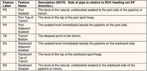
Feature Labels:
The table below shows the standard Feature Label codes used by VisualSoft, and which are used in calculations for depth of burial, mean adjacent level etc. Other labels may also be used, and the data will be displayed but will not be included in any automatic calculations.
Data Example
200604260429480,1146025788.00,4.374532,398835.530,6494818.140,125.023,336.200,0.965,-0.630,1.370,2.180,-0.805,402,...5.19,1.53,4,PS,-5.11,2.65,SS,3.85,1.71,PA,-1.43,2.23,SA,0.16,2.12
200604260431384,1146025898.38,4.372958,398835.556,6494816.565,124.309,248.516,0.965,0.450,2.040,2.595,-0.720,402,-8.11,2.68,...6.34,2.50,4,PS,-4.03,2.68,SS,4.93,2.51,PA,-0.34,2.76,SA,1.25,2.76